Week 3
Computer Controlled Cutting
This week's task involved two key parts: Vinyl Cutting and Laser Cutting with Parametric Design. In the vinyl cutting segment, we created and cut a design using the vinyl cutter. For laser cutting, we designed, cut, and documented a parametric construction kit, ensuring precise adjustments for laser kerf—the material lost during cutting. Additionally, we aimed to enhance our design by incorporating non-flat elements for a more complex and functional outcome.
Group Assignments
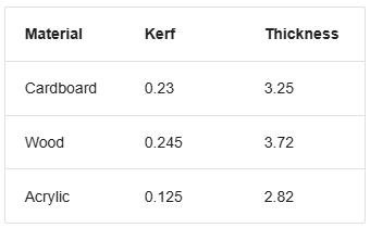
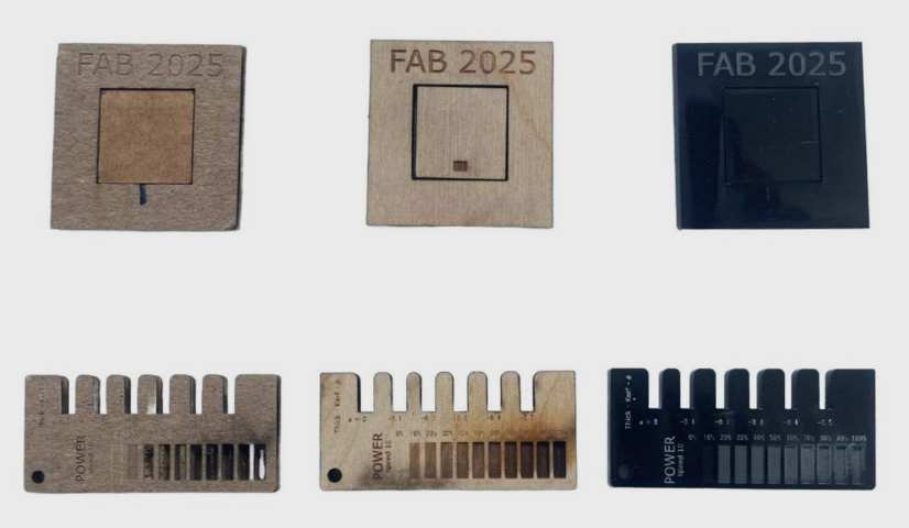
Our group had a great learning experience, starting with lab safety and learning to use the laser cutter. We understood the importance of safety measures like wearing gloves, using proper respiratory masks, and following the correct steps while operating the machine. We also learned how to calculate kerf values and use them in CAD modeling to improve accuracy. It was interesting to see how kerf width changes with different materials and how we needed to adjust our designs accordingly. Parametric design helped us create flexible models, which we applied while making a fitment testing jig. By designing three jigs with different materials, we learned how to fine-tune our designs for each one. This hands-on experience improved our technical skills and problem-solving abilities, making us more confident in working with laser cutting and design.
For more info visit our group assignment page.
Link : Week03 Group Assignment
Vinyl Cutting
Vinyl cutting is a fascinating process that lets us turn 2D images or vector designs into precise cuts on vinyl using a computer-controlled CNC machine equipped with a small but sharp blade.
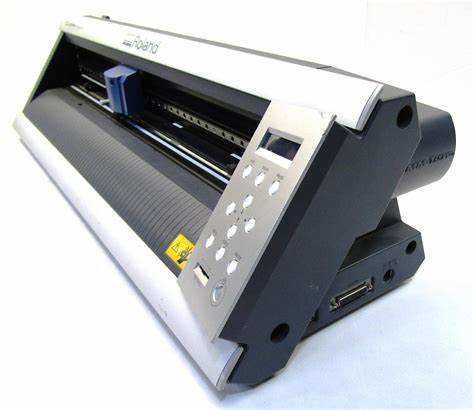
Roland GX-24 Vinyl Cutter
In our lab, we use the Roland GX-24 for vinyl cutting. There are two main types of vinyl cutters: active and passive.
- Active cutters use a servo-controlled mechanism to rotate the blade.
- Passive cutters, like the Roland GX-24, rely on the natural movement of the cutting head—the blade turns in the direction of motion, similar to how a roller coaster wheel follows a track.
Even though it’s a passive cutter, the Roland GX-24 is fast, precise, and servo motor-driven, making it ideal for high-quality vinyl cutting.
Setting Up the Machine
The GX-24 uses sharp, pointed blades positioned at a 45° angle to the cutting direction. Depending on the material and design complexity, we can also use 30° or 60° blades, but 45° is the standard in our Fab Lab.
Adjusting Cutting Parameters
When working with vinyl, two key settings need fine-tuning:
- Force – How hard the blade presses onto the vinyl.
- Speed – How fast the cutter moves.
Both settings depend on the thickness and quality of the vinyl. If the force is too high, it can cut through the backing paper or damage the blade. To get the best results, we ran a test cut using different force levels.
The goal of the test was to cut out a circle while leaving the inner square intact—this helps check whether the blade is cutting just deep enough without tearing through the material.
Optimal settings for our vinyl:
- Force: 100g
- Speed: 1 cm/s
If the speed increases, the force may need adjusting to prevent uncut edges or overcuts. Luckily, the machine’s menu makes it easy to tweak these settings, and there’s even a test cut button for quick calibration.
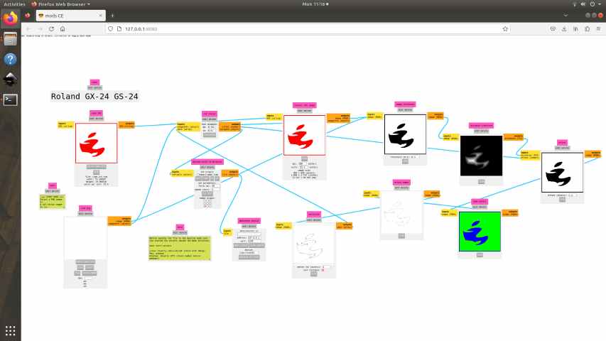
Using FAB Mods & Cutting the Design with the Roland GX-24
To send designs to the vinyl cutter, we used FAB Mods, an open-source web app that acts as a machine driver. Instead of using the Roland software, FAB Mods connects directly to the cutter via WebSocket technology.
Link : mods CE
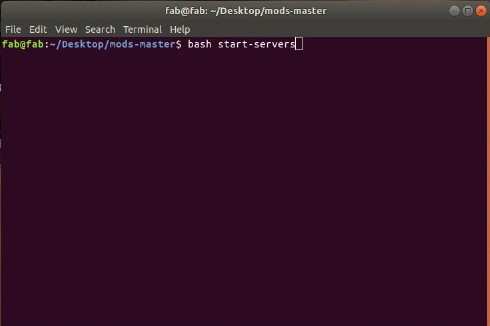
In Linux first right click on the mode_master File that should be downloaded from GitHub
Then give the command ”bash start-server “
Then right click select Programs
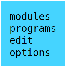
- Then click open program
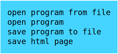
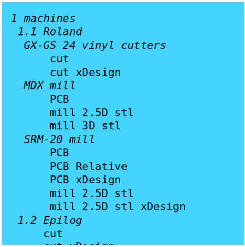
- Then select the machine in my case GX 23 vinyl cutter
- Once my SVG or PNG file was ready, I loaded it into FAB Mods for the Roland GX-24.
I turned on the Roland GX-24 and loaded a vinyl roll for the first cut.
Loading the Vinyl
To ensure the vinyl fed through the machine properly:
- I adjusted the roller guides to align with the white marked area (since unmarked areas don’t provide enough grip).
- I selected the "Roll" option on the machine, allowing it to automatically measure the vinyl’s length.
- In FAB Mods, I calculated the toolpath based on the default blade diameter.
- Clicking "View" in the Vectorize module opened a preview of the toolpath in a new tab.
Additional modules helped adjust offsets and cutting details as needed.
To make sure the cutter started at the correct position:
- I moved the cutting head to the desired starting point.
- I set the new origin by long-pressing the Origin Set button on the machine.
- With everything ready, I sent the file to the Roland GX-24 by clicking "Send File to Device" in FAB Mods.
- I repeated the process for my second vinyl, cutting each layer separately before carefully peeling them from the roll.

- By the end, I had successfully created a multi-color vinyl logo using the Roland GX-24 and FAB Mods
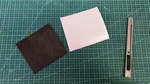
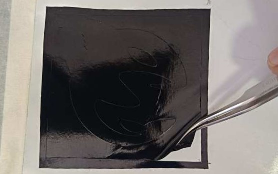
- The next step is to remove the unwanted parts from the vinyl from the piece.
- After removing all the unwanted parts from the sticker and use a transfer paper to stick to pate in the final location.
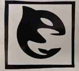
- Repeat the same steps for the second color and stick it to the final location, Try to use the some reference to align the second sticker since the transfer paper is transparent.
This is the final result

Parametric design and laser cutting
Parametric design in Fusion 360 refers to a design approach where dimensions, constraints, and relationships are defined using parameters, allowing the model to automatically update when changes are made.
The second part of this week assignment was to make a parametric design and cut it using laser cutting.
- First step of my design was to make a basic idea
- After this I made the basic parameters for the design.

- I have made parameters like kerf material thickness,slot length,sides of shapes etc.And I have also used polynomial equations for some parameters too.
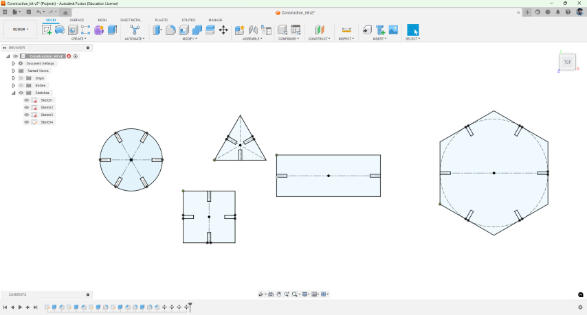
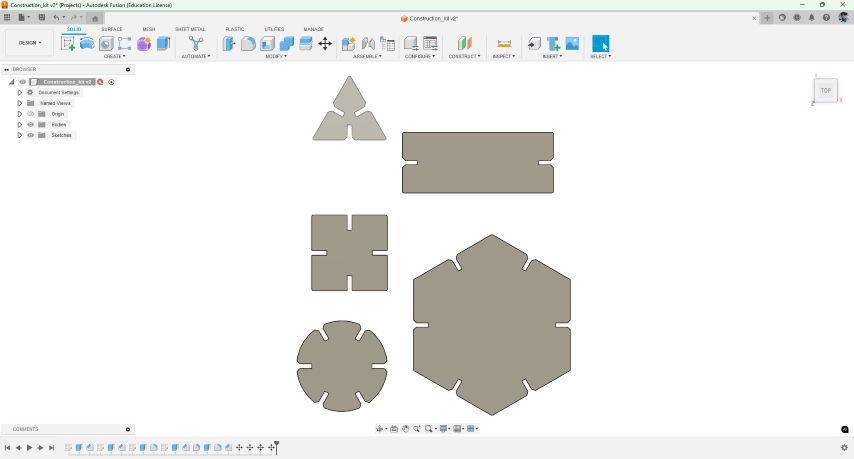
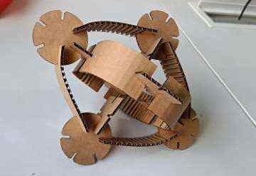
- Using these parameters I made some basic parts for the construction kit. I made a sere that shapes are constructed using the parameters so it can be easily adjusted easily.
- Then I prototyped the design to make sure that all the fitments are correct then made the necessary changes and optimize the parameters
- The I finalized the design and imported this design into Inkscape and added the design for the engraving
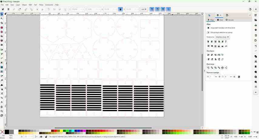
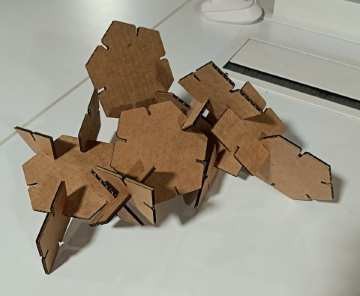
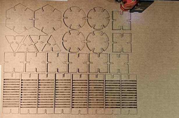
- Then using the laser cutter I made made the final cut. Also made sure to arrange the parts properly to reduce the material consumption, Before cutting make sure that the design properly fits inside the cardboard
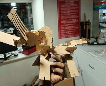
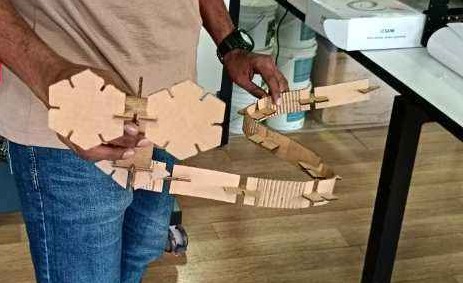
Innovation
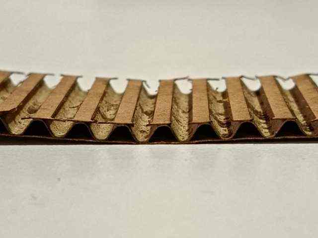
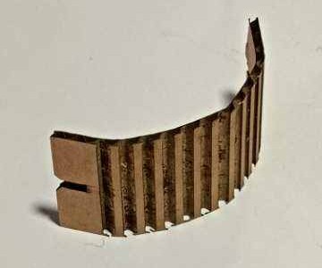
My idea was to make a flexible component in my construction kit which can be used to make flexible assemblies like shock absorbers etc.
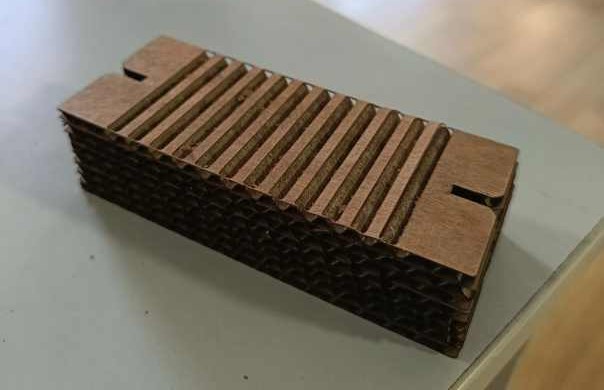
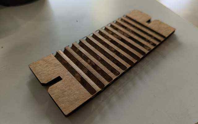
This was made my engraving and removing material from one side of the cardboard sheet to make it flexible since it have corrugated sheet in between it have a elastic property.
By leaving more material while engraving it increases the rigidity of the material and reduces the flexibility.
Models I Made
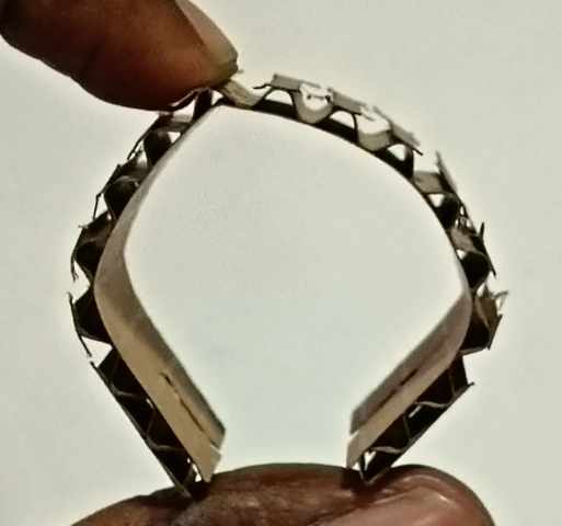
Simple flexible structure
This was a simple structure that is comparatively very flexible when compared to a cardboard parts.
Snake 🐍
Simple cardboard snake my by assembling parts from parametric construction kit.
Lazy Dog 🐕🦺
cardboard dog made made by assembling parts from parametric construction kit.I gave the name “Lazy Dog” because it won’t stand due to its flexible legs 😁 .