Week 4
Embedded Programming
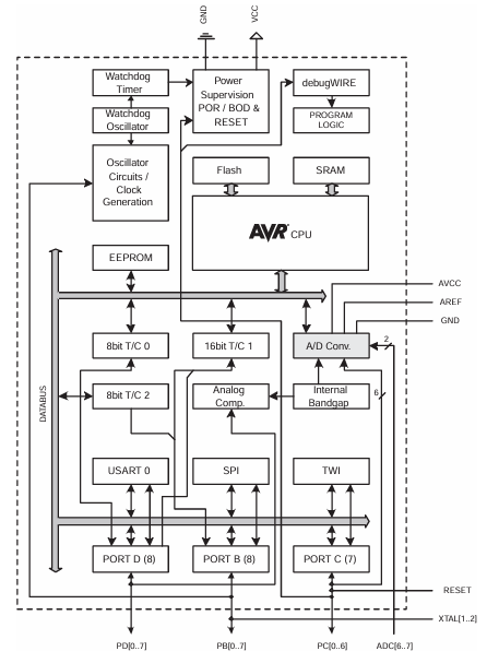
The group assignment involves demonstrating and comparing the toolchains and development workflows for different embedded architectures. Individually, you are required to review the datasheet of your microcontroller, write a program for it, and simulate its operation. The program should enable interaction with local input and/or output devices and facilitate communication through remote wired or wireless connections. For extra credit, you can test the program on a development board and explore different programming languages or development environments.
Group Assignments
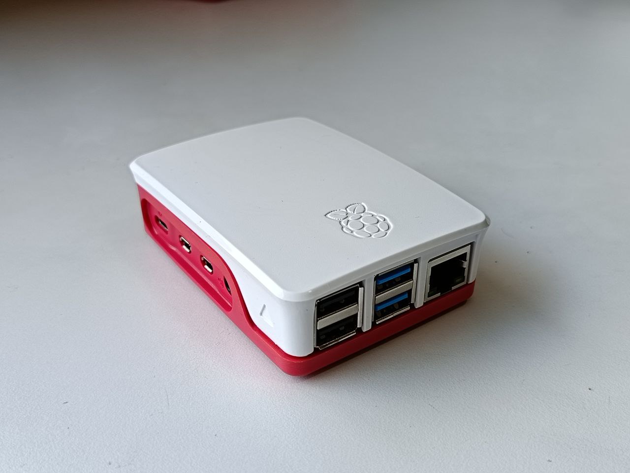
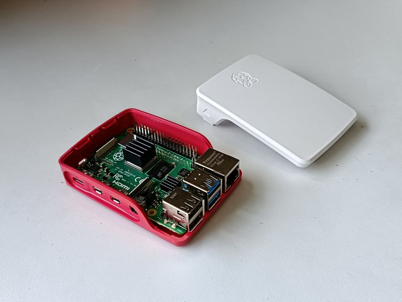
This week's group assignment involved exploring of multiple micro controllers and I explored Rasp berry pi and maid a basic program using python.
For more info visit our group assignment page.
Link : week04 Group Assignment
WOKWI
Wokwi is a online simulation platform used for simulating and testing of programs in a micro controller. Micro controllers like ESP32, Raspberry Pi Pico etc. are available for for testing and simulations. It is a good platform for beginners for testing for more advanced simulations its better to use a more advanced simulator.
From my observations using micro python is more efficient compared to c++ in Wokwi, I think it is because Micro python executes the program line by line and c++ is taking a lot of time for simulating and it was failing multiple times .
PICO
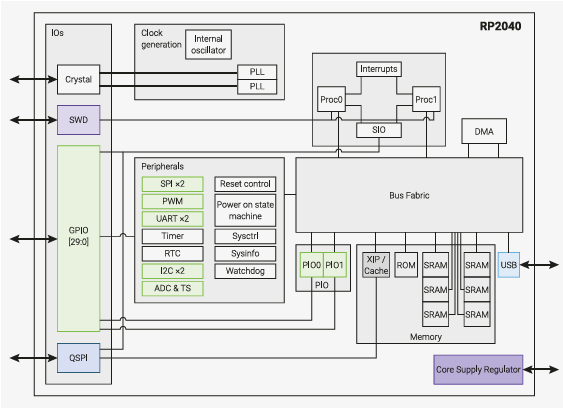
The Raspberry Pi Pico is a small microcontroller board by the Raspberry Pi . It uses a RP2040 microcontroller chip. It has a dual-core ARM Cortex-M0+ processor it can run at speeds up to 133 MHz, 264 KB of SRAM, and 2 MB of onboard flash memory for storing your programs. IT also have the Programmable I/O (PIO) subsystem, The PIO subsystem offloads work from the main CPU, freeing it up for other tasks.
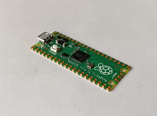
Pico is compact and can be easily used for DIY projects, It has 26 GPIO pins and it also supports UART, SPI, I2C, and PWM, It also have a 12 bit analog-to-digital converter (ADC),a built-in temperature sensor, and low-power sleep modes to save energy
](../images/week04/pico-pinout.svg)
Image source : https://projects.raspberrypi.org/en/projects/getting-started-with-the-pico
You can program it in multiple languages, including MicroPython, C/C++, and CircuitPython, and it connects to your computer via a Micro-USB port for easy programming.
To learn more : Getting started with Raspberry Pi Pico | Micropython | Coding projects for kids and teens
Technical Specifications
Microcontroller Chip
- Chip: RP2040 (Dual-core ARM Cortex-M0+)
Documentation Link : Pico-series Microcontrollers - Raspberry Pi Documentation
Clock Speed
- Max Speed: 133 MHz
Memory
- Flash Memory: 2MB
- SRAM: 264KB
GPIO and Analog Pins
- Total GPIO Pins: 26
- Analog Input Pins: 3
Communication Protocols
- UART: 2
- I2C: 2
- SPI: 2
- I2S: Yes
- PWM: Available on all GPIO pins
- PIO: 2 Programmable I/O
Analog-to-Digital Converter (ADC)
- 12-bit ADC (3 channels and 1 internal temperature sensor)
Electricals
Voltage Requirements
- Microcontroller Operating Voltage: 1.8V to 3.3V
- Board Power Supply: 1.8V to 5.5V (via VSYS)
- USB Power: 5V
GPIO Electrical Characteristics
- Output Voltage:
- High: 3.3V
- Low: 0V
- Maximum GPIO Sink/Source Current:
- Per Pin: 12mA max
- Total GPIO Current: 50mA max
- Input Voltage Tolerance:
- Maximum GPIO Input Voltage: 3.3V
- Higher voltages require a voltage divider or level shifter
Documentation Link : Pico-series Microcontrollers - Raspberry Pi Documentation
ChatGPT Prompt : What are the electrical specifications for the Raspberry Pi Pico?
PICO Wokwi Simulation
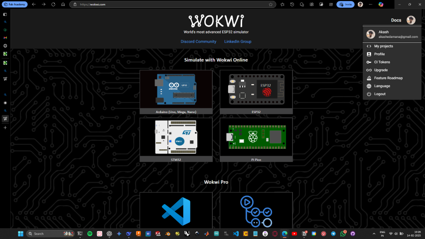
- From the top left corner click on the profile photo and open the drop down window and then to create a new simulation select “My Projects”
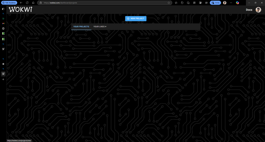
- Then from the new window click on the new project button, then scroll down and select the board
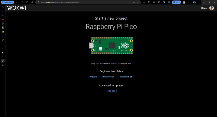
- In my case I am using a Raspberry pi pico and from the window select the language being used, Here i am using Micro Python
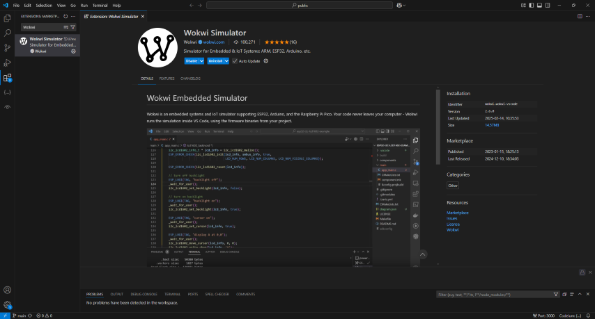
- Also there is an VS Code Extension for wokwi For more Info : Getting Started with Wokwi for VS Code | Wokwi Docs
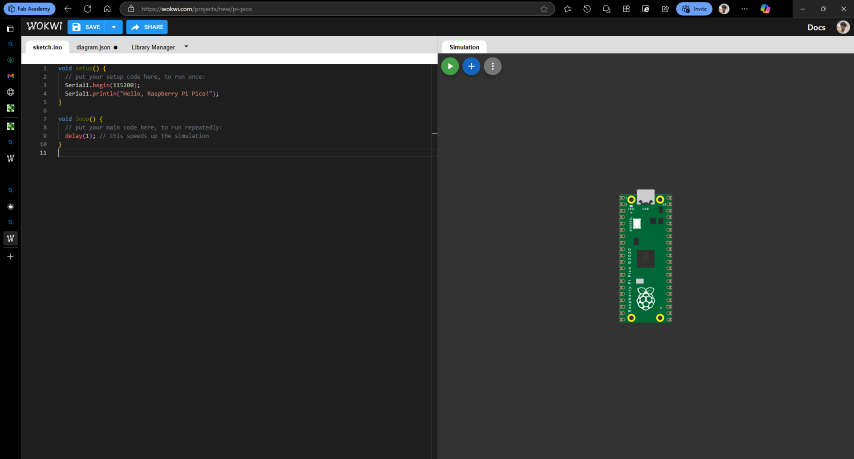
- This is the interface that opens, here in the left side the top green button stars the simulation, The blue plus button is used for adding peripherals into the simulation
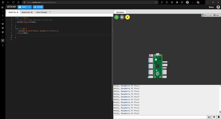
“Hello, Raspberry Pi Pico” Simulation Using C++
- This is the first program I wrote, this is to print a string in a loop.
- For this project no external peripherals are needed.
      void setup() { // put your setup code here, to run once.
      Serial1.begin(115200);//This command is used to initiate communication with serial monitor.
      }

    void loop() {
      // put your main code here, to run repeatedly
      Serial1.println("Hello, Raspberry Pi Pico!");
      //This commands used to print the output in serial monitor,
      //The "Println" used to pint in the next line.
      delay(2000); // this speeds up the simulation
    }
- This is the output i received
Blinking Internal LED using Micro Python
- The next program I made was a simple blink internal led and for this I referred the examples from Wakwi. Link : https://wokwi.com/pi-pico
      import time #This to import time library
      import machine #This is to import the machine library
      led machine.Pin (25,machine.Pin.OUT) #This is to define the pin
      Count = 0
      while True: //This is to create a loop
          print(Count)
          time.sleep(1)
          led.value(1) #This is to make the LED pin state to high
          time.sleep(2) #This to add a delay
          led.value(0) # This is to make the LED pin state to LOW
          time.sleep(2)
- This the final output
Blinking External LED using Micro Python
- Here I simulated the blinking of an LED connected to Pin 27
- Here I have added an external resister depending on the calculate value. Link : https://ohmslawcalculator.com/led-resistor-calculator
      import time
      import machine
      led machine.Pin(27,machine.Pin.OUT)
      Count = 0
      while True:
        print(Count) //This is to print the count
        time.sleep(1) //This is to add a delay
        led.value(1) //This is to make the LED pin state to high
        time.sleep(2)
        led.value(0) //This is to make the LED pin state to low
        time.sleep(2)
- This is the Final Result
Neo pixel LED using Micro Python
The NeoPixel LEDs are RGB LED lights with a built driver IC that makes these lights addressable and programmable.
- Here I have made a simple program for running a neo pixel LED
- I have refereed a existing example for making this program Link : WokwiMakesRaspberry Pi Pico on Wokwi - Online ESP32, STM32, Arduino Si…
      import time
    from neopixel import Neopixel #Form importing Neopixel Library
    pixels Neopixel(17, 0, 6, "GRB")
    colors = [          # Here I have defined all the colours for the LED in Matrice
    (6xb6, 0xe4, 0x30),
    (0x42, 0xd1, ехеθ),
    (0x00, 0x00, 0xff),
    (0xff, 0x00, 0x00),
    (0x00, 0xff, 0x00),
    ]
    pixel_index = 0 # Define the value of the variable to 0
    color_index = 0

    while True:
        pixels.set_pixel(pixel_index, colors[color_index])
        pixels.show()
        #print(pixel_index, colors[color_index]) this referred from the neo pixel library
        pixel_index +-1
        if pixel_index == 16:
            pixel_index=0
            color_index = (color_index + 1) % 4 #This used for indexing the color one by one
        time.sleep(0.1)
- This is the Final Result
Neo pixel LED Color control using Micro Python
- First step was to design the circuit.
- From the top left section click the plus button to add new component
- Depending upon the component make the necessary connections.
- Here i gave a external pull_Up resister.and connected the
- some micro controllers have a pull up resister inbuilt.
- Here I made a program for neo pixel LED in which when a switch is triggered the color changes.
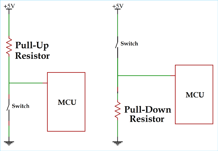
Pull-Up Resistor
What it does: It pulls the wire up to a high voltage (1) when nothing else is connected.
Pull-Down Resistor
What it does: It pulls the wire down to a low voltage (0) when nothing else is connected.
      import time
      from neopixel import Neopixel
      from machine import Pin
      pixels = Neopixel(17, 0, 6, "GRB")

      Switch = Pin(26, Pin.IN, Pin.PULL_DOWN) # Define a pin and gave the value to a variable
      value = 0 # defined the value as 0

      colors = [  // Here I have defined all the colours for the LED in Matrice
        (0xb6, 0xe4, 0x30),
        (0x42, 0xd1, 0xe0),
        (0xff, 0x00, 0x00),
        (0x00, 0xff, 0x00),

      ]

      pixel_index = 0
      color_index = 0
      while True: # This is the main loop

          pixels.set_pixel(pixel_index, colors[color_index])
          pixels.show()
          pixel_index += 1
          value = Switch.value()
          print("switch",value)
          time.sleep(.2)
          if pixel_index == 16: #Here when the Pixel index becomes 16 it reset's to 0
            pixel_index = 0
            time.sleep(0.1)
          if value == 1 : # when the switch is triggered the colour value is indexed
           color_index = (color_index + 1) % 4  // This indexes the color one by one
- This is the final result
Arduino IDE
The Arduino software (IDE) is an open source software, which is used to programme the Arduino boards, and is an integrated development environment, developed by arduino.cc. Allow to write and upload code to Arduino boards.I had already used Arduino IDE so i hade it already installed
For setting up follow this link : https://www.tutorialspoint.com/arduino/arduino_installation.htm
Arduino Uno
Arduino UNO is a microcontroller board based on the ATmega328P. It has 14 digital input/output pins (of which 6 can be used as PWM outputs), 6 analog inputs, a 16 MHz ceramic resonator, a USB connection, a power jack, an ICSP header and a reset button. It contains everything needed to support the microcontroller; simply connect it to a computer with a USB cable or power it with a AC-to-DC adapter or battery.
](../images/week04/Figura-2-Imagen-de-la-placa-Arduino-Uno-R3-Fuente-Proyecto-Arduino.jpg)
Image source : Imagen de la placa Arduino Uno R3. Fuente: Proyecto Arduino.... | Download Scientific Diagram
](../images/week04/word-image-338-768x559.jpg)
Image source : Arduino Uno Pinout Guide
Technical Specifications
Micro controller Chip
- Chip: ATmega328P
Documentation Link : raspberrypi.com/documentation/microcontrollers/pico-series.html
Clock Speed
- Speed: 16 MHz
Memory
- Flash Memory: 32KB
- SRAM: 2KB
- EEPROM: 1KB
GPIO and Analog Pins
- Total GPIO Pins: 14
- PWM Pins: 6 (D3, D5, D6, D9, D10, D11)
- Analog Input Pins: 6 (A0 - A5)
Communication Protocols
- UART: 1 (Serial communication on pins 0 & 1)
- I2C: 1 (SDA on A4, SCL on A5)
- SPI: 1 (MISO - D12, MOSI - D11, SCK - D13, SS - D10)
Analog-to-Digital Converter (ADC)
- Yes, 10-bit ADC (6 channels, 0-1023 range)
Electrical Specifications
Voltage Requirements
- Operating Voltage: 5V
- Input Voltage : 7-12V
- Input Voltage : 6-20V
Logic Voltage
- 5V logic level
GPIO Electrical Characteristics
- Output Voltage:
- High: 5V
- Low: 0V
- Maximum GPIO Sink/Source Current:
- Per Pin: 40mA max
- Total Max Current for all I/O Pins: 200mA
- 3.3V Pin Max Current Output: 50mA
- Input Voltage Tolerance:
- Digital Pins: 0V to 5V
- Analog Pins: 0V to 5V
Documentation Link : docs.arduino.cc/hardware/uno-rev3/
ChatGPT Prompt : What are the electrical specifications for the Arduino Uno?
Blink LED Using Arduino Uno
- Here I have used c++ to make a simple LED blinking program
- Here i have used a resister depended on the calculated value of resistance Link : https://ohmslawcalculator.com/led-resistor-calculator
void setup() { pinMode(A1, OUTPUT);//Defining A1 pin as output } void loop(){ digitalWrite(A1, HIGH); //Making the pin High delay(1000); //Giving a delay of 1 second digitalWrite(A1, LOW); //Making the pin LOW delay(1000); }- This is the circuit diagram
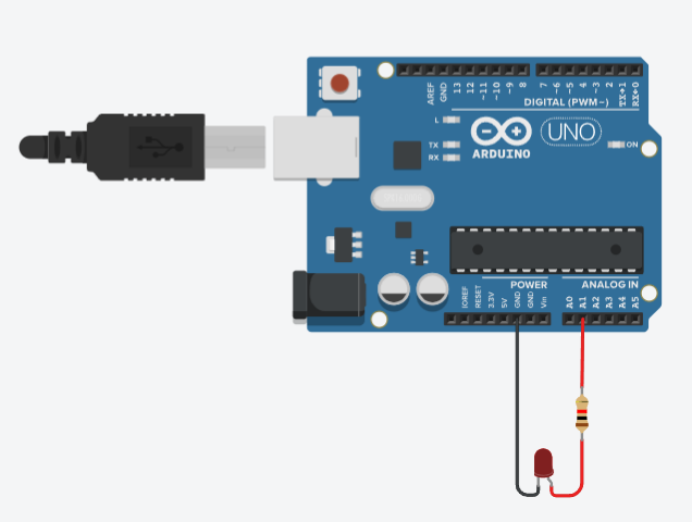
- This is the Final output
LED Brightness control Using Potentiometer
- Here I have used a potentiometer to control the brightness of the brightness of an led
- While testing this i learned about PWM signal and also understood that there are specific pins in Uno that can give a PWM signal which is represented by “~”
#define LED 11 //Here the pin's are defined #define Potentiometer A0 void setup() { Serial.begin(9600); pinMode (LED, OUTPUT); //here Pin is defined as out put } void loop() { int Brightness = analogRead(Potentiometer); //Reading analog the value from potentiometer analogWrite(LED, Brightness); //Out puting analog value to the LED Serial.println(Brightness); //print the value of brightness in serial monitor }- This is the circuit
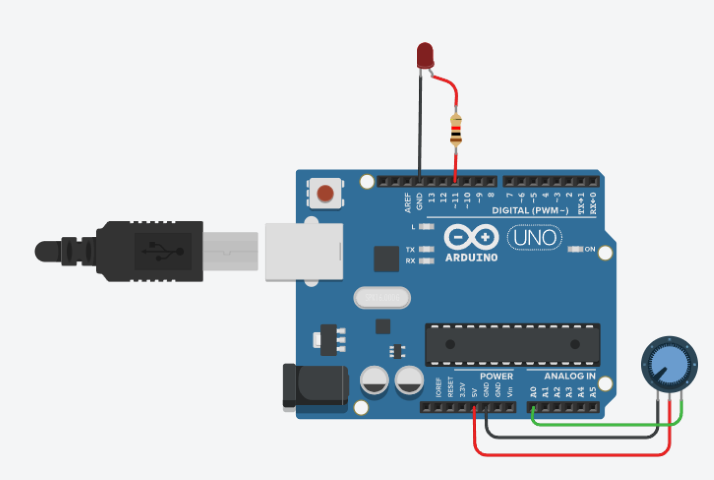
- Final output
Servo Angle Control Using potentiometer
- The next thing i tried out was controlling the angle of servo using potentiometer
#define Servo 11 void setup() { Serial.begin(9600); //This command is used to initiate communication with serial monitor pinMode(Servo, OUTPUT); } void loop() { int Input = analogRead(A1); //Reading analog the value from potentiometer int Angle = map(Input,0,1023,0,360); // Here map is used connect the voltage pwn level to angle Serial.println(Angle); //print the value of angle in serial monitor analogWrite(Servo, Angle); //Out puting analog value to the Servo }- This is the circuit
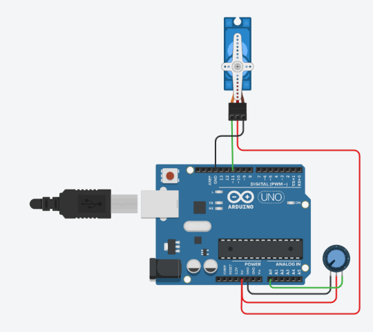
- This is the final output
What is debugging
Debugging is the process of finding and fixing problems in a program. It involves a step by step process of figuring out what’s going wrong, and then fix it so everything works Properly.Serial monitor, serial plotter and devices like oscilloscope are used for debugging
Serial Monitor
"The serial monitor is a tool used for debugging. It can be used for showing outputs and giving inputs into a program while it is running. It is commonly used in embedded systems development with microcontrollers.
C++
In Arduino (C++), the Serial.print() and Serial.println() functions are used to send data to the serial monitor.
MicroPython
In MicroPython, the print() function is used to send data to the serial monitor. Additionally, you can use the uart module for more advanced serial communication.
Conclusion
I explored programming on the Raspberry Pi and worked with the Pico and Seeed Studio boards using MicroPython. I also experimented with the Arduino Uno in the Arduino IDE and tried out the Thonny IDE. This experience gave me a better understanding of different development environments and programming workflows for embedded systems.